Field Engineering

Engineering Case Studies

Real-world machinery diagnostics, vibration analysis, and predictive maintenance projects — documented with methodology, findings, and outcomes.

Turbine-generator set vibration analysis
16 Channels
Simultaneous Data Points
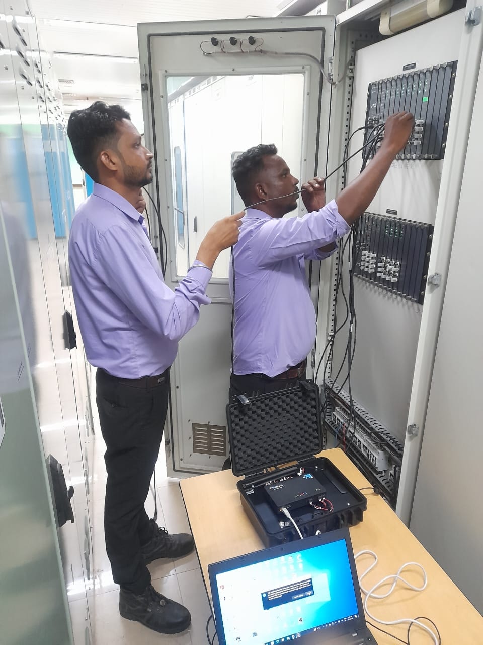
Engineers connecting 16-channel data collector hardware to proximity probe buffer outputs at power plant

Data Collector Setup
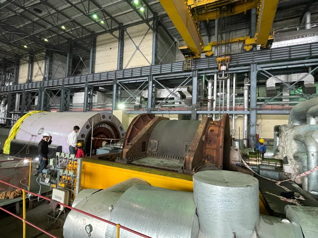
Turbine-generator set at power plant during 16-channel vibration analysis

Turbine-Generator — Power Plant

16-channel vibration analysis diagram — landscape overview
16-channel vibration analysis schematic diagram — portrait
Vibration AnalysisPower GenerationTurbo Machinery — Power Plant

Sixteen Channel Vibration Analysis of Turbo Machinery from Power Plant

Sixteen channel vibration analysis of turbo machinery from a power plant — data collector hardware connected via cables from buffer outputs of proximity probes, collecting all vibration readings and running speed (RPM) at a single instance of time, then transferred to software for further analysis.

Challenge

The power plant required a complete vibration snapshot of their turbo machinery at a single instance of time, capturing all measurement points simultaneously to eliminate phase errors caused by sequential data collection.

Approach

Data collector hardware was connected via cables from the buffer outputs of the proximity probes to the data collector. The data collector took real-time data from the proximity probes installed on the turbo machinery, collecting all vibration readings for a given instance of time along with the running speed (RPM) for measuring the phase. Once all data was collected, it was transferred to software for further analysis.

Outcome

Complete vibration health assessment of the power plant turbo machinery delivered with accurate phase data across all 16 channels. Identified developing condition trends and provided prioritized maintenance recommendations to prevent unplanned shutdown.

Methodology

1Data collector hardware connected via cables from buffer outputs of proximity probes to the data collector
2Real-time data acquisition from proximity probes installed on the turbo machinery
3All vibration readings collected for a given instance of time across all 16 channels
4Running speed (RPM) recorded simultaneously for phase measurement
5Collected data transferred to software for further analysis
6Spectral analysis, waveform review, orbit plots, and engineering report with findings

Our Process

How We Conduct Vibration Analysis

Our structured diagnostic process for sixteen channel vibration analysis of turbo machinery — from hardware connection at the buffer outputs through to software analysis and final engineering report.

Step 01

Cable Connection to Buffer Outputs

Data collector hardware is connected via cables from the buffer outputs of the proximity probes — already installed on the turbo machinery — to the data collector. No dismantling required.

Step 02

Real-Time Data Acquisition

The data collector takes real-time data from the proximity probes installed on the turbo machinery, collecting all vibration readings for a given instance of time across all 16 channels.

Step 03

RPM & Phase Measurement

Running speed (RPM) is recorded at the same instance as the vibration data, providing the phase reference needed for synchronous analysis and accurate imbalance diagnosis.

Step 04

Data Transfer & Software Analysis

Once all data is collected, it is transferred to software for further analysis — spectral review, waveform evaluation, orbit plots, and a detailed engineering report with findings and recommendations.

Ready to Diagnose Your Rotating Equipment?

Our engineers are available for on-site vibration analysis, multi-channel data acquisition, and comprehensive machinery health assessments.